Electroanatomical Mapping of the Urinary Bladder
Article information

Abstract
A noncontact mapping system (EnSite) was used for electroanatomical mapping of the bladder simultaneously with pressure flow study in three women with lower urinary tract symptoms. We selected the periods of obvious detrusor activity. Data were processed to remove baseline drift, and an envelope of electrovesicography (EVG) data was created. The correlation coefficient for the correlation between between the EVG envelope and the detrusor pressure (Pdet) was calculated. Bladder geometry was successfully created in all 3 patients. Simultaneous recording of EVG and pressure flow data was successful in 1 patient. Scatter plots were made of the highest correlation coefficient, showing a positive correlation between the Pdet and the envelope, and negative correlation between abdominal pressure (Pabd) and the envelope. Minimal electrical activity could be observed. Significant weak to moderate correlation coefficients were found for the correlations between Pdet and EVG and between Pabd and EVG.
Overactive bladder (OAB) syndrome is defined as “urinary urgency, often with frequency and nocturia, in absence of obvious bladder pathology” [1]. The actual pathophysiologic mechanisms of OAB are still to be identified. Arrhythmic electrical activity has been detected in the bladder wall of OAB patients [2,3], and it was suggested that the interstitial cells of Cajal were the source of the electrical activity of the bladder [4]. In cardiology, 3-dimensional (3D) mapping systems are used that are capable of projecting the electrical activity of the endocardium on electroanatomical maps, which allow to locate the origin and propagation paths of cardiac arrhythmias [5]. Electroanatomical mapping of the bladder might reveal crucial information about bladder pathophysiology and new management strategies for OAB. For instance, electroanatomic mapping might indicate specific locations for onabotulinum toxin A injections, thereby increasing the effectiveness of treatment and decreasing the costs. In this study, we present the developments of an electroanatomic map of the urinary bladder using 3D mapping system (EnSite, St. Jude Medical Inc., St. Paul, MN, USA).
CASE REPORT
Electroanatomic maps of the urinary bladder were developed using a noncontact mapping system (EnSite), which consisted of a roving catheter, a noncontact multielectrode array (MEA) 64-electrode basket, and a custom designed amplifier system, with custom designed software, connected to a Silicon Graphics workstation. The MEA catheter had 2 ring electrodes located proximal and distal to the basket. The reference electrode was located 16 cm distal to the basket. In cardiology application, a geometric model of the heart is realized by moving the roving catheter against the inner wall of the atrium. The current sensed by the proximal and distal ring electrodes mounted on the MEA catheter created a location specific voltage distribution.
The local Medical Ethics Committee Commisie Mensgebonden Onderzoek approved the study under number 46832.091.13/METC 2013/279. Three women aged 34, 56, and 82 years with lower urinary tract symptoms were included in the study.
The first patient was a 34-year-old woman with OAB symptoms (urge incontinence); her urodynamic study revealed detrusor overactivity (DO). The second patient was a 53-year-old woman with chronic neurogenic nonobstructive urinary retention. She had been using a Brindley stimulator since 2001. The third patient was an 82-year-old woman with OAB. She complained of urgency and urge incontinence; the urodynamic study revealed DO.
The measurements were performed in the supine position. The bladder was drained using a 14-Fr catheter, through which 200 mL of NaCl 0.9% was injected into the bladder. The roving catheter was introduced through the urethra to create the bladder geometry. The roving catheter was replaced by an urodynamic pressure catheter together with an MEA catheter. The electrovesicography (EVG) and the vesical pressure recordings were started simultaneously.
During the measurement, EVG data were sampled at a frequency of 1.2 kHz; the recorded signals were unipolar, with a bandpass filter between 0.1 and 300 Hz. The measurements were performed using the EnSite system, simultaneously with pressure flow study of the bladder using Urodynamics Systems (Medical Measurement Systems B.V., Enschede, The Netherlands). The electrical signals obtained from the EnSite system and the pressure signals obtained from the urodynamic system were manually synchronized. We selected the periods with obvious detrusor activity, either DO or voiding act. Data were visually inspected and processed to remove baseline drift. An envelope of a segment of the EVG data was created using the absolute values of the mean of all channels recordings. The correlation coefficient for the correlation between the envelope of the EVG data and the pressure signal of the bladder was calculated. The P-values were calculated by using two-tailed t-test with a significance level of 0.05.
Bladder geometry was created successfully in all 3 patients (Fig. 1). Simultaneous recording of EVG and pressure flow data was successful in one patient. Data segments with detrusor pressure activity (DO and/or voiding act) were selected; the related EVG and detrusor pressure (Pdet) recording are shown in Fig. 2. Scatter plots were made of the delay with the highest correlation coefficient, showing a positive correlation between the Pdet and the envelope, and negative correlation between abdominal pressure (Pabd) and the envelope (Fig. 3).
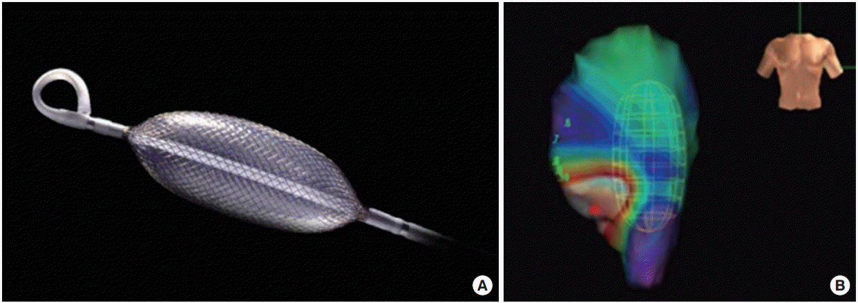
(A) Ensite array catheter. (B) The bladder geometry model with the catheter (indicated by the green basket) inside the bladder. Green, blue, and purple colors are assigned to large amplitude electrograms produced by viable muscle tissue. While red color is assigned for regions of low voltage as previously described in cardiology application by Hegland et al. [5].
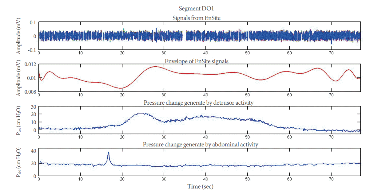
Session II, segment DO1. The upper trace shows the raw EnSite signal, the bladder muscle activity measured in millivolt over time. The second trace presents the envelope of the EnSite signal created during our analysis (the processed data). The third trace shows the detrusor pressure measured over time with the Medical Measurement Systems (MMS B.V., Enschede, The Netherlands). The lowest trace presents the change of the abdominal pressure, measured over time with the MMS system. DO1, the first interval/episode of detrusor overactivity detected on urodynamic curves; Pdet, detrusor pressure; Pabd, abdominal pressure.
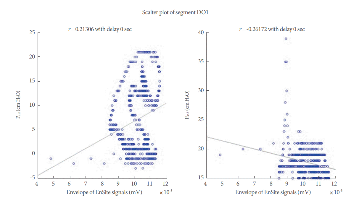
Scatter plot for segment DO1. This figure shows the relationship between the detrusor pressure and the electrical activity measured with the EnSite system. On the left side is depicted the scatter plot of the detrusor pressure and the envelope of the Ensite signal and on the right side is depicted the scatter plot of the abdominal pressure and the envelope of the Ensite signal. The line represents the regression line and r is the regression value. The blue circles are the data points, pressure values corresponding to the envelope signal. DO1, the first interval/episode of detrusor overactivity detected on urodynamic curves; r, regression value; Pdet, detrusor pressure; Pabd, abdominal pressure.
DISCUSSION
To our knowledge, the current study is the first attempt to measure the electrical activity within the urinary bladder in humans. Some previous studies reported signals measurements: Shafik et al. [3] reported bladder signals of 1.6 mV, while Hashitani et al. [6] reported bladder signals of 72 mV. These amplitudes were derived from direct intracellular measurements. The measured signal in the current study did not exceed 0.1 mV. This might be explained by the fact that the measured signals were estimated by the EnSite software, which was originally developed to measure electric activity of the heart, which has a different geometry from the urinary bladder. Another possibility to explain these low amplitudes could be the low conductivity of the saline fluid used to fill the bladder.
The maximal distance for the EnSite system to measure the electrical activity in the heart is 5 cm. However, it is not clear whether this is true for the bladder. Furthermore, as showed in Fig. 1, the catheter is not located in the middle of the bladder, but rather lies against the bladder wall. This deviation from the central position of the MEA catheter could lead to recording of one side only, the side closer to the catheter bladder activity.
Low bladder volumes might lead to direct contact between the MEA catheter and the bladder wall, which might result in motion artifacts. Therefore, we tried to maintain a maximal distance of 3.6 cm between the catheter tip and the bladder wall, which corresponds to a volume of about 200 mL. Technical artifacts might be enormous for an accurate interpretation, especially in different bladder volumes and thicknesses. The tip of the electrode might be monitored with a camera using the video urodynamic study.
The calculated correlation coefficients varied from 0.007 to 0.21. Both positive and negative correlations were found, although negative correlations were not expected. Ideally, the correlation coefficients of one segment should be significant for the detrusor pressure and insignificant for the abdominal pressure.
The smooth muscle architecture in healthy urinary bladder is homogenous. This might not be the case of the pathologic bladder. However, the aim of this study was to test the possibility of developing the electroanatomical mapping for the bladder. In the next phase of the study, we will try to examine the electroanatomical features of the urinary bladders in healthy and disease status.
Electroanatomical mapping of the bladder might reveal crucial information about bladder pathophysiology for new management strategies for OAB. For instance, electroanatomical mapping might indicate specific locations for the onabotulinum toxin A injections, thereby increasing the effectiveness of treatment and decreasing the costs. Electroanatomical mapping of the bladder might be useful to differentiate the underlying pathologies in patients with bladder underactivity.
Electroanatomical mapping of the bladder is feasible with minimal discomfort to the patient. Minimal electrical activity could be observed, and significant weak to moderate correlation coefficients were found for the correlation between detrusor and abdominal pressures, and EVG. The electrical propagation activity over the bladder wall could not be detected using the current method.
Notes
Fund Support
The study was supported by Allergan.
Research Ethics
The local Medical Ethics Committee Commisie Mensgebonden Onderzoek approved this study under number 46832.091.13/METC 2013/279.
Conflict of Interest
No potential conflict of interest relevant to this article was reported.